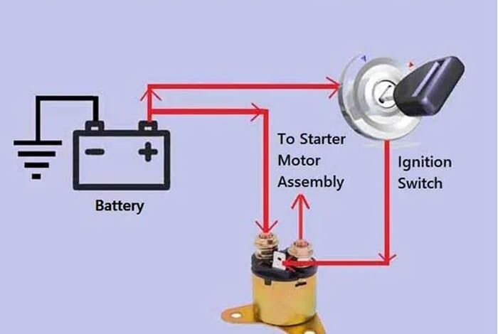
The wires that go to the starter solenoid are the battery cable and the ignition switch wire. These wires are essential for the starter solenoid to function properly.
When it comes to the wiring of a starter solenoid, it’s crucial to understand the specific connections to ensure the proper functioning of the vehicle. Whether it’s for an ATV, motorcycle, Ford Mustang, or any other vehicle, the correct wiring is vital for the starter solenoid to work effectively.
Understanding the wiring diagram and knowing which wires go to the starter solenoid is essential for maintaining the vehicle’s electrical system. We will discuss the significance of the starter solenoid, the essential wires involved, and the potential consequences of incorrect wiring. Understanding the wiring of the starter solenoid is crucial for vehicle owners and enthusiasts alike.
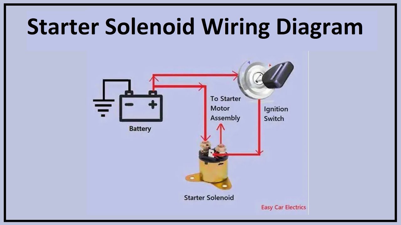
Credit: m.youtube.com
Introduction To Starter Solenoids
The starter solenoid plays a crucial role in a vehicle’s ignition system, serving as the bridge between the battery and the starter motor. Understanding the function and components of the starter solenoid is vital for maintaining and troubleshooting a vehicle’s starting mechanism.
Role Of The Starter Solenoid In Vehicle Ignition
The starter solenoid acts as a relay switch that controls the flow of electrical current from the battery to the starter motor. When the ignition key is turned, the solenoid engages, allowing high amperage to be delivered to the starter motor, which initiates the engine’s cranking process. This critical function ensures the smooth and efficient starting of the vehicle.
Components Of A Starter Solenoid
A typical starter solenoid consists of several key components, including:
- Electromagnetic Coil: This coil is responsible for creating a magnetic field when energized, allowing the solenoid to actuate.
- Contacts: These are the points where the electrical circuit is completed, allowing current to flow to the starter motor.
- Plunger: The plunger is connected to the electromagnetic coil and moves to bridge the contacts when the solenoid is energized.
- Housing: The outer casing that encloses and protects the internal components of the solenoid.
Understanding these components is essential for diagnosing and resolving any issues related to the starter solenoid.
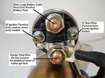
Credit: www.corvetteforum.com
Identifying Solenoid Wires
Identifying solenoid wires involves correctly mapping out which wires connect to the starter solenoid. It’s crucial to refer to a wiring diagram for precise guidance on this electrical connection. Properly identifying and connecting the wires ensures the starter solenoid functions effectively.
Color Coding And Wire Identification
When it comes to identifying solenoid wires, one of the easiest methods is to look for color coding and wire identification. In most cases, the wires will have a specific color code that corresponds to their function. For example, the red wire may be for the positive battery terminal, while the black wire is usually the negative. Other wires may be color-coded depending on their function, such as the yellow wire for the ignition switch or the green wire for the starter motor.Common Wire Types And Their Functions
Another method for identifying solenoid wires is to understand the common wire types and their functions. These wire types include power wires, ground wires, signal wires, and control wires. Power wires deliver power to the solenoid, while ground wires provide a return path for the current. Signal wires are used to transmit information to the solenoid, while control wires are used to control the operation of the solenoid.Example Diagram
To help illustrate the wiring of a starter solenoid, the following example diagram shows the typical wiring connections for a solenoid. In this example, the solenoid has four terminals: two large terminals for the power and ground wires, and two small terminals for the control and signal wires.| Terminal | Wire Color | Function |
|---|---|---|
| 1 | Red | Positive Battery Terminal |
| 2 | Black | Negative Battery Terminal |
| 3 | Yellow | Ignition Switch |
| 4 | Green | Starter Motor |
Wiring The Starter Solenoid
Discovering the correct wiring for the starter solenoid involves identifying which wires connect to the solenoid. Understanding the diagram can provide clarity on the specific wires needed for proper installation and functionality of the starter solenoid.
Step-by-step Wiring Instructions
When wiring the starter solenoid, follow these simple step-by-step instructions to ensure correct connections:
- Disconnect the Battery: Before starting any wiring, disconnect the battery to prevent any electrical accidents.
- Locate the Starter Solenoid: Find the starter solenoid in the engine compartment for wiring.
- Identify the Wires: Differentiate between the main power wire and other connections for proper wiring.
- Connect the Main Power Wire: Attach the main power wire to the designated terminal on the solenoid.
- Secure the Connections: Ensure all connections are tight and secure to prevent any loose wiring issues.
- Reconnect the Battery: Once all wiring is complete, reconnect the battery and test the starter solenoid.
Connecting The Main Power Wire
One critical aspect of wiring the starter solenoid is connecting the main power wire correctly. This wire is responsible for supplying power to the starter motor, enabling the engine to start smoothly.
To connect the main power wire:
- Locate the Terminal: Identify the terminal on the starter solenoid designated for the main power wire.
- Strip the Wire: Strip the end of the main power wire to expose the conductor for a solid connection.
- Attach the Wire: Securely attach the stripped end of the wire to the designated terminal on the solenoid.
- Tighten the Connection: Ensure the connection is tight to prevent any power loss or electrical issues.
- Check for Secure Fit: Double-check that the main power wire is securely connected to the starter solenoid terminal.
Ignition Input Wire
When it comes to starting your vehicle, the ignition input wire plays a crucial role in the process. This wire is responsible for transmitting the electrical signal from the ignition switch to the starter solenoid, activating the starter motor and initiating the engine’s combustion cycle.
Purpose Of The Ignition Wire
The ignition input wire serves as the conduit for the electrical signal that triggers the starter solenoid. When the ignition key is turned, the wire carries the signal from the ignition switch to the solenoid, which then engages the starter motor. This seamless transmission of electrical energy is essential for the smooth initiation of the vehicle’s engine.
How To Connect The Ignition Wire
Connecting the ignition wire involves identifying the appropriate terminal on the starter solenoid and ensuring a secure and reliable connection. It is crucial to match the ignition wire to the designated terminal on the solenoid to guarantee proper functionality. Securing the connection with a reliable fastening method, such as a bolt or a connector, is essential to prevent any disruptions in the electrical signal transmission.
Safety And Precautions
When working with the starter solenoid and its associated wiring, it’s essential to observe safety precautions to prevent electrical hazards and potential accidents. By following the electrical safety tips and checking for proper wire insulation, you can ensure a secure and hazard-free working environment.
Electrical Safety Tips
- Disconnect the Battery: Before beginning any work on the starter solenoid or its wiring, disconnect the vehicle’s battery to eliminate the risk of electrical shock or short circuits.
- Wear Insulated Gloves: When handling the wiring or making connections, wearing insulated gloves can protect you from accidental electric shocks.
- Avoid Water Exposure: Work in a dry environment and avoid exposure to water or moisture, as these can conduct electricity and increase the risk of electrical accidents.
- Use Insulated Tools: Insulated screwdrivers and tools should be used to prevent accidental contact with live wires or terminals.
- Inspect for Damage: Before proceeding, carefully inspect the wiring for any signs of damage, wear, or fraying, and replace any compromised components.
Checking For Proper Wire Insulation
Proper wire insulation is crucial to prevent electrical shorts and ensure the safe operation of the starter solenoid. When examining the wiring, pay close attention to the following:
- Color Coding: Ensure that the wires are correctly color-coded and that there are no exposed or bare sections.
- Insulation Integrity: Check for any cracks, breaks, or deterioration in the insulation, as these can lead to potential electrical hazards.
- Secure Connections: Verify that all connections are securely insulated and free from any exposed metal, preventing accidental contact.
Credit: forum.ih8mud.com
Troubleshooting Common Issues
If you’re troubleshooting common issues with diagramming the wires to the starter solenoid, ensure proper connection of the positive terminal to either wire, as polarity does not matter on solenoid valve coils. It’s important to follow the correct wiring diagram and understand the starter circuit for a successful setup.
Diagnosing Connection Problems
Diagnosing connection problems is crucial for resolving starter solenoid issues. Check for loose, corroded, or damaged wires. Ensure all connections are secure and properly attached.Solutions For Frequent Solenoid Issues
To address common solenoid issues, inspect the wiring diagram to identify correct wire placement. Test the solenoid and associated components for proper functionality. Consider replacing worn-out parts if necessary.Tools And Equipment Needed
To diagram what wires go to the starter solenoid, you’ll need basic tools and equipment such as a wire stripper, electrical tape, wire connectors, and a wrench. These tools will help you safely identify and connect the correct wires to the starter solenoid for efficient functioning.
Tools and Equipment Needed Wiring a starter solenoid requires certain tools and equipment to ensure the job is done correctly. Here are the essential tools you need to have on hand:Essential Tools For Wiring A Solenoid
| Tool | Description |
|---|---|
| Wire Strippers | A tool used to remove insulation from the end of a wire. |
| Screwdriver | A tool used to tighten or loosen screws on the solenoid. |
| Wrench | A tool used to tighten nuts and bolts on the solenoid. |
| Multimeter | A tool used to measure voltage, current, and resistance on the solenoid. |
| Electrical Tape | A type of tape used to insulate and protect electrical connections. |
Additional Helpful Resources
If you’re unsure about how to wire a starter solenoid, there are plenty of resources available to help you. Here are a few:- Technical Articles – Ford Starter Solenoid Wiring
- Starter Solenoid Wiring Diagram | EdrawMax | EdrawMax Templates
- Wired Up: Starter Wiring Mistakes You Need To Avoid
- How to Wire a Starter (With Example Diagrams) – In The … CarParts.com
- Easy Car Electrics
Final Setup And Testing
Once the starter solenoid and all the associated wires are correctly installed, it’s crucial to perform thorough testing to ensure everything is functioning as it should. This final step ensures that the starter solenoid is properly connected and ready for use.
How To Test The Solenoid Post-installation
After completing the installation, you can test the solenoid to verify its functionality. This involves using a multimeter to check for proper voltage and continuity, ensuring that all connections are secure and that there are no loose or damaged wires. Additionally, testing the solenoid’s response to the ignition switch will help confirm that it engages and disengages correctly.
Adjustments And Final Checks
Following the initial testing, it’s essential to make any necessary adjustments to the wiring or connections. This includes tightening any loose terminals, securing the wires to prevent interference with other components, and ensuring that all electrical connections are properly insulated to prevent short circuits. Once adjustments are made, a final visual inspection should be conducted to verify that everything is in place and properly secured.
Frequently Asked Questions
What Wires Go Where On A Starter Solenoid?
To wire a starter solenoid, connect the positive battery cable and starter motor wire to the appropriate terminals.
Does It Matter Which Way A Solenoid Is Wired?
The polarity of a solenoid valve coil does not matter; you can connect either wire to the positive terminal.
What Wire Goes From Ignition To Starter?
The wire that goes from the ignition to the starter is known as the IGN or ignition input wire. It’s usually yellow or red and signals the car’s ignition system to turn on. The brown or yellow wire is the Starter (ST) wire.
Does The Positive Wire Go To The Solenoid?
Yes, the positive wire does go to the solenoid.
Conclusion
Understanding the wiring of a starter solenoid is crucial for proper vehicle function. Follow wiring diagrams carefully for a successful installation. Remember, wire colors may vary, but polarity usually does not matter. Ensure a safe and efficient connection for optimal performance.